
Origin of Strong Scarring of Wave Functions in Quantum Wells in a Tilted Magnetic Field.
Semiclassical Theory of Magnetotransport through a Chaotic Quantum Well
Quantum wells in tilted fields: Semiclassical analysis and experimental evidence for effects "beyond" periodic orbits.
Canted Antiferromagnetic Phase in a Double Quantum Well in a Tilted Quantizing Magnetic Field.

|
Poincaré surface of section at the collector barrier for q = 38°, b = 3.7° , g = 1.17° .
The axes are the scaled velocities in the plane transverse to the electric field (see inset). The positions of one of the three fixed points of
different period-three orbits are indicated by arrows (others are symmetrically placed). Note that a large period-one
stable island near the center of the SOS also leads to strong localization of the quantum wave functions by the familiar
procedure of local torus quantization. Because of its isolation from the relevant unstable PO’s these stable contributions can
be easily distinguished from scars. The inset shows a schematic of the geometry with our axis conventions.
(Narimanov and Douglas Stone [1998]) |

|
Bifurcation diagrams for the relevant period-two (a) and period-three (c) orbits. The axis b (defined in text)
may be regarded as the scaled magnetic field; the vertical axis is the ux coordinate of one of the fixed points in the SOS
associated with the orbit as indicated by the arrow in the inset.
( b), (d ) Plots of the trace of the monodromy (stability) matrix for the corresponding orbits; shaded area (
|Tr[Mg]| < 2 denotes stability region. Orbits denoted (1,2)-,
(1,3)- remain slightly unstable over a large variation of
b, leading to strong scarring. The notation ( m, n )±
used for the periodic orbits represents the topology of the orbit
( m collisions with the emitter barrier and n collisions with the collector
barrier per period; +, - indicates that the orbit is stable, unstable just before its disappearance by inverse bifurcation).
(Narimanov and Douglas Stone [1998]) |

|
(a)-(c) Examples of wave functions scarred by unstable (1,2)- orbit (a),
(1,3)- orbit (b), and (1,5)- orbit (c);
y-z projections of orbits are superimposed.
(d)-(f) "Scar strength" H vs the scaled action S(en)/h of the unstable
orbit which scars the eigenstate of energy en.
The three cases shown are (a) (1,2)- orbit, ( b) (1,3)- orbit, (c) (1,5)- orbit.
The arrows indicate the values of b for the tangent bifurcation, which give birth to the periodic orbits.
Note that when increasing action (or energy) the tangent bifurcation at higher
b ~ 1/e occurs at the lower action side.
The peaks of the scar strength below the tangent bifurcation are due to the "ghost effect".
Scaled actions below the bifurcation points were obtained by linear extrapolation of the (approximately linear) function.
(Narimanov and Douglas Stone [1998]) |
Semiclassical Theory of Magnetotransport through a Chaotic Quantum Well

|
Bifurcation diagrams for the four period-two orbits relevant to the peak doubling in the interval u
q = 29° - 34°
(see text). Colored lines indicate y coordinate of the single collision with the emitter; these lines coincide at bifurcations.
q = 29°
(a) indicates behavior before the exchange bifurcation; q = 31° ( b) and 34° (c) after.
Shading represents the localization lengths lm associated with the relevant orbits [(1,2)2 and (1,2)1 for (a),
and (1,2)2* and (1,2)1 for (b), (c)]. Hatched region denotes semiclassical
width of emitter state; overlap indicates a large contribution to the tunneling
current.
(Narimanov et. al [1998]) |
|
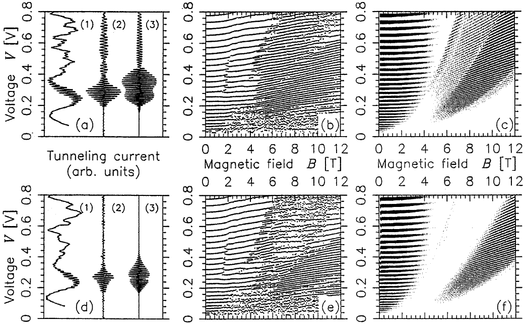
(a),(d): Resonant tunneling I-V traces for q = 31°, q = 34° at B = 8 T.
Trace (1) is raw experimental data, trace (2) is same data, filtered to retain only period-two oscillations, trace (3) is semiclassical prediction.
The modest discrepancies in the shape of the envelope of the amplitude of the oscillations is due to the inaccuracy of the quadratic semiclassical theory near
the bifurcation which occurs around 0.3 V at 8 T.
(b),(e): Peak positions vs voltage and magnetic field, determined from multiple sets of experimental I-V data at q = 31°,34°. (c),(f): Semiclassical I-V oscillations for same, note gray scale indicates relative amplitudes, not just peak positions. Note disappearance of high voltage oscillations at q = 34° due to movement of (1,2)2 orbit away from accessibility after the exchange bifurcation . (Narimanov et. al [1998]) |
Quantum wells in tilted fields: Semiclassical analysis and experimental evidence for effects "beyond" periodic orbits

|
Experimental data plotting the positions of maxima in the I(V) traces as a function of magnetic field B.
The curves are parabolas of constant V/B2 , which correspond approximately to
constant classical dynamics. They are labeled with the value of e
= F/B2 . PD1, PD2, and PD3 denote period-doubling regions.
The features associated with the changeover of the quantum number of the torus series with the strongest current amplitude are indicated by
the torus K quantum numbers. q = 11°. q = 27°.
(Saraga and Monteiro [1998]) |

|
(a) Main periodic orbits which domi-nate the current oscillations at q = 11° and
q = 27°. t0 gives the main period-one current.
t2 is an unstable PO, which coalesces with t0 in a series
of tangent bifurcations. S1 1 and S' are 3-bounce orbits responsible for some of the period-doubling regions.
(b) Poincare surfaces of section for q = 27° for different values of e = F/B2 . The dynamics becomes progressively more chaotic as e decreases. (Saraga and Monteiro [1998]) |

|
Comparison between experimental and theoretical line profiles at
q = 11 o showing
effects of approximate scaling dynamics.
(a) Experiment: set of I-V traces (reduced current) showing characteristic line profiles roughly along parabolas of constant e = F/B2. . The period-doubling regions PD1 and PD2 are shown along with the ‘‘ghost’’ region where the results are not due to a real PO. The arrows indicate the semi-classical limit. (b) Theory: smoothed theoretical spectra. The quantum number N is proportional to magnetic field B. The range N=12-42 corresponds to voltage range 0.121.1 V. With decreasing e, right asymmetric profiles ( ~ 19 000) evolve into symmetric perioddoubled profiles at the bifurcation. Below the tangent bifurcation ( ~ 6500) the ‘‘ghost’’ has a weak sinusoidal profile. PD2 is mainly due to S1 but has substantial period one interference, indicating that t0 is still accessible. (Saraga and Monteiro [1998]) |

|
Experimental traces at q = 27° showing the broad ‘‘plateau’’ of period-doubled current corresponding closely to the range
of the quantum maximum rather than the range of the semiclassical current. This indicates that contribution is not
due to real PO over about half the experimental period-doubled range (below
e ~ 8000 and above e ~ 18 000).
(Saraga and Monteiro [1998]) |
Canted Antiferromagnetic Phase in a Double Quantum Well in a Tilted Quantizing Magnetic Field

|
Positions of the magnetocapacitance minima, or of the active current component maxima, at a temperature of 30 mK
for different tilt angles:
(a) q = 0°, (b) q = 30°, (c) q = 45°, and (d) q = 60°. (Khrapai et. al [2000]) |